Guide
Natural gas metering systems
What a metering station is, what it is made of, which meters and station types exist, how they are calibrated — and what we do, from engineering to commissioning.
What a metering system is, and why it is needed
A metering system, or metering station, is the installation that measures how much natural gas passes a point in the network. It sits where gas changes hands: at a country’s entry point, where two networks connect, at the delivery to a distribution network or to a large consumer such as a power plant.
Because invoices are issued from this measurement, it is called custody transfer metering, and it must be accurate, repeatable and auditable. A small systematic error on a large flow becomes a large amount of money every year.
Gas is usually billed in energy (kWh or MWh), not volume. So the station does not measure volume alone: it measures pressure and temperature, to convert the volume to base conditions, and the gas composition, to calculate its calorific value. Volume at base conditions times calorific value gives the energy.
What a station is made of
Select a part to see it on the diagram.
On the diagram: Inlet and outlet valves
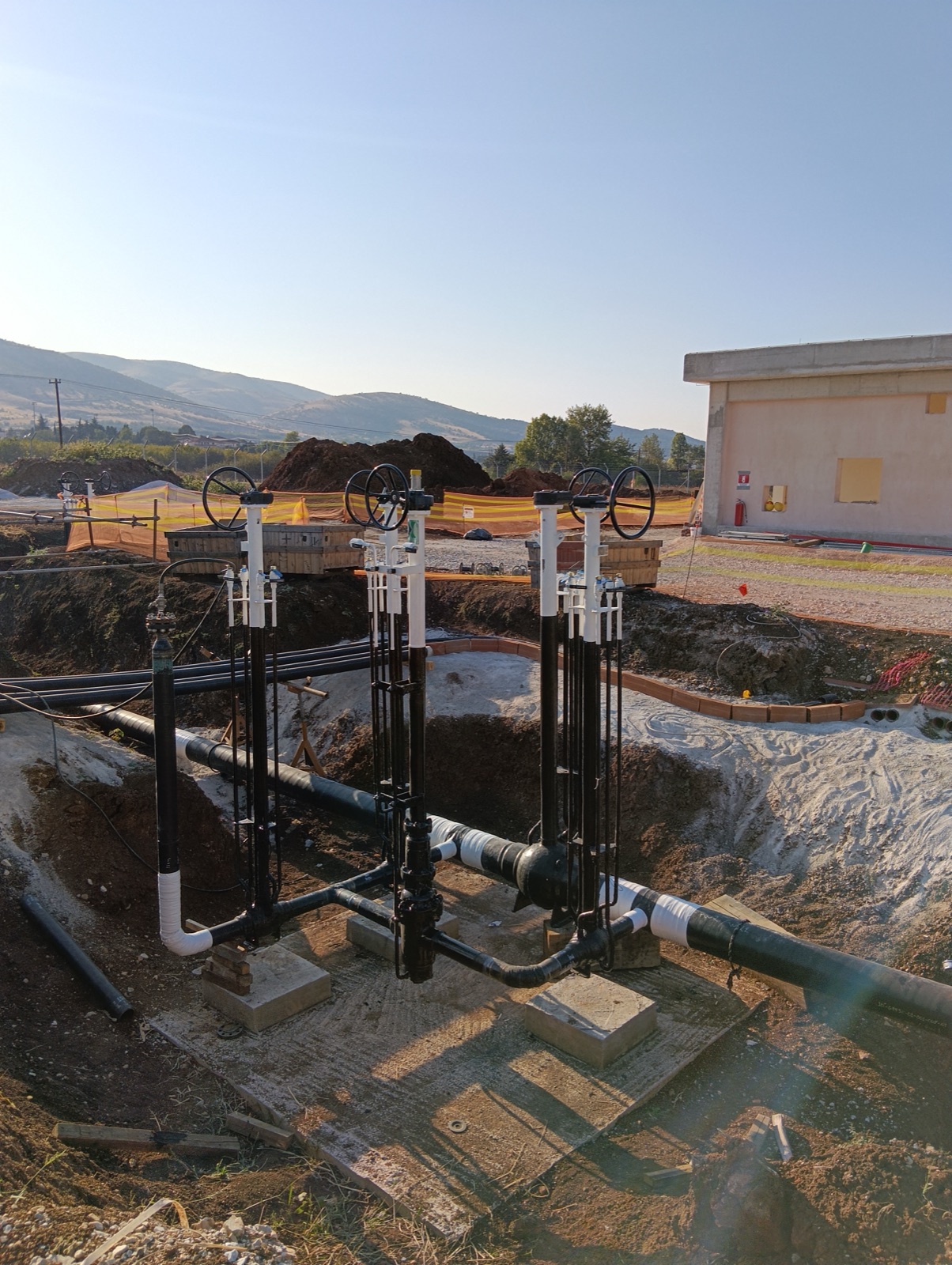
They isolate the station from the pipeline, for maintenance or in an emergency. They are often buried, with the stem and operator above ground, and often have an electric actuator for remote operation.
They remove dust, rust and liquids carried by the gas, so that meters and regulators do not wear or measure wrongly. There are usually two, one on standby, so a filter can be cleaned without stopping the flow.
When pressure drops, the gas cools (the Joule–Thomson effect). Preheating raises its temperature first, so that after regulation valves do not freeze and hydrates do not form. It is needed where the station also reduces pressure.
The header splits the gas into two or more parallel runs, each with its own meter. One runs on duty and one stands by, or all share the flow. Each run has valves at both ends, so it can be taken out for checks or a meter change.
A perforated plate or tube bundle upstream of the meter. It corrects the flow profile disturbed by bends and valves, so that the meter measures a flow like the one it was calibrated with. Together with the straight lengths before and after the meter, it is set by the manufacturer and the standards.
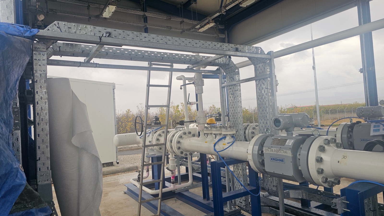
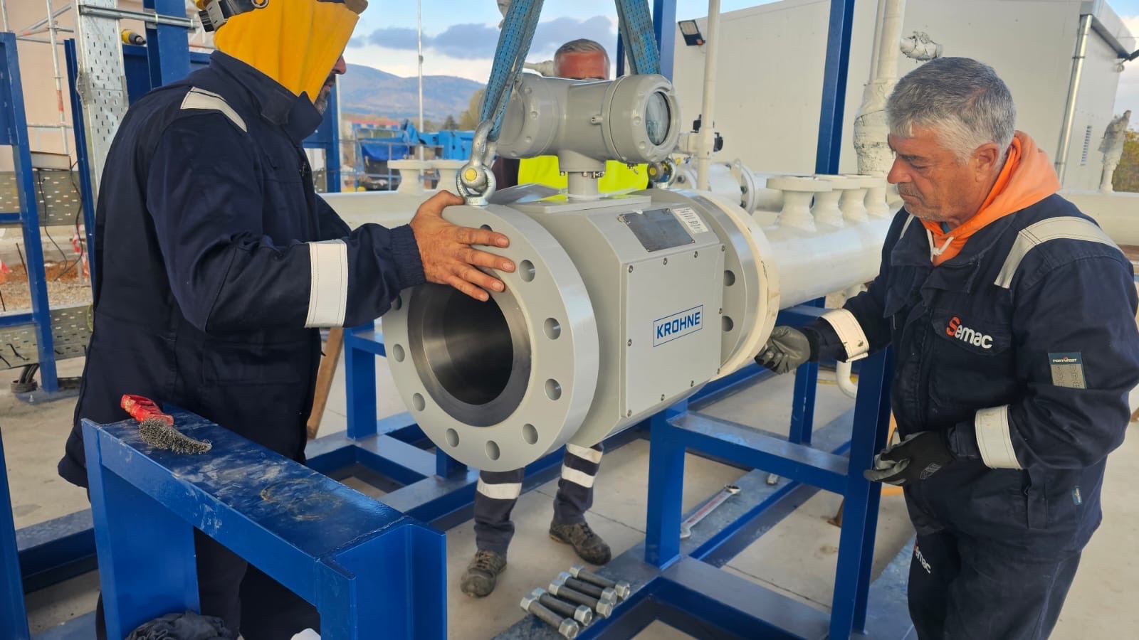
The heart of the run: it measures the volume, or the mass, of the gas passing through. Large transmission stations mostly use ultrasonic meters; smaller ones use turbine or positive displacement meters. The types are described below.
They measure the pressure and temperature of the gas at the meter. With these two values the flow computer converts the measured volume into the volume the gas would have at base conditions.
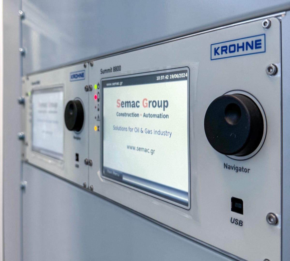
It completes the measurement: it takes the meter data, pressure, temperature and gas composition, and calculates volume at base conditions, mass and energy, both instantaneous and totalised. It also keeps the audit trail of every change and every alarm.
It analyses a gas sample and returns its composition: methane, ethane, propane, nitrogen, carbon dioxide and others. The calorific value and density needed for the energy are calculated from the composition. One chromatograph can serve every run of the station.
In metering and regulating stations, regulators reduce the pressure to the value of the downstream network. Slam-shut valves and relief valves protect the network if a regulator fails.
A line around the metering section that keeps the supply going during maintenance. Gas passing through it is not measured, so the bypass stays closed and sealed, and opens only under the network operator’s rules.
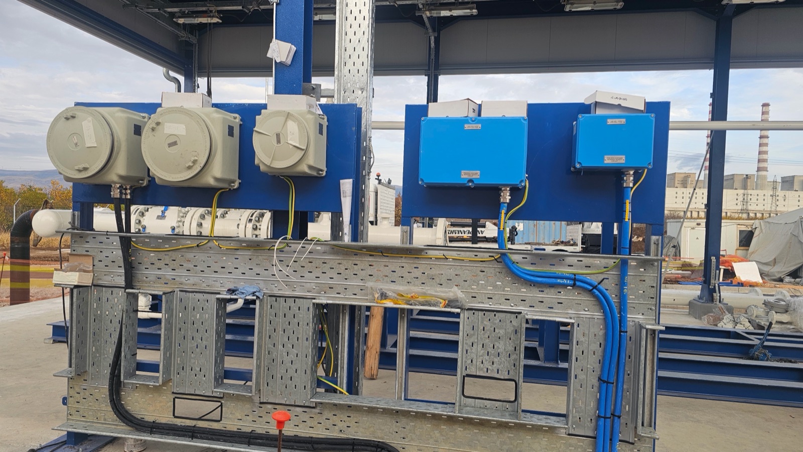
The remote terminal unit (RTU) sends measurements, states and alarms to the operator’s control centre, and receives commands for the remotely operated valves. Uninterruptible power supplies (UPS) keep metering and communications running if mains power is lost.
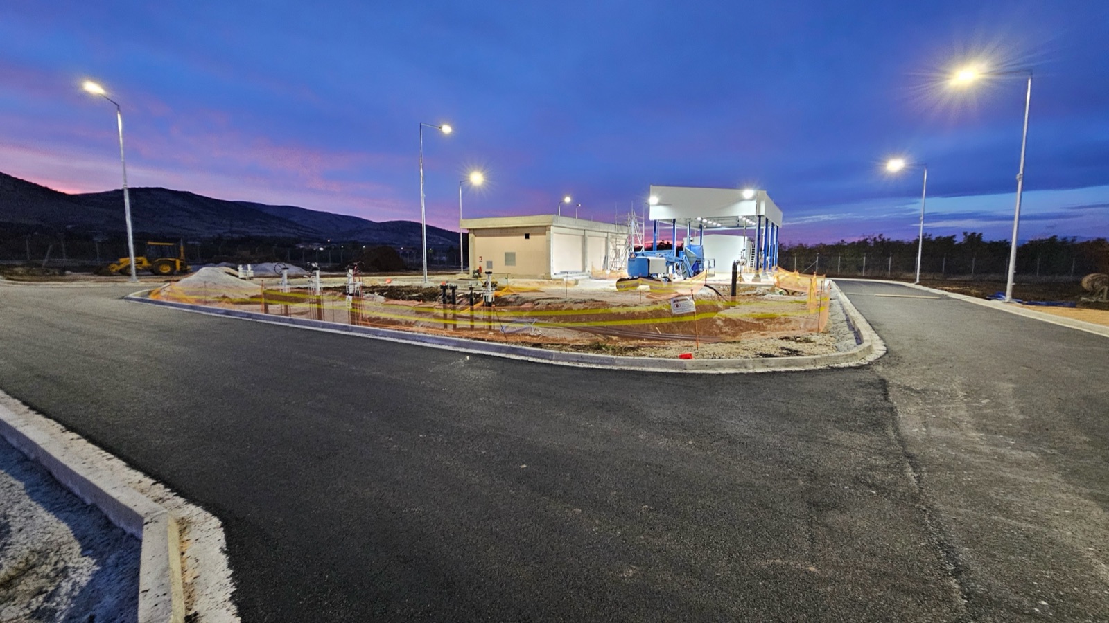
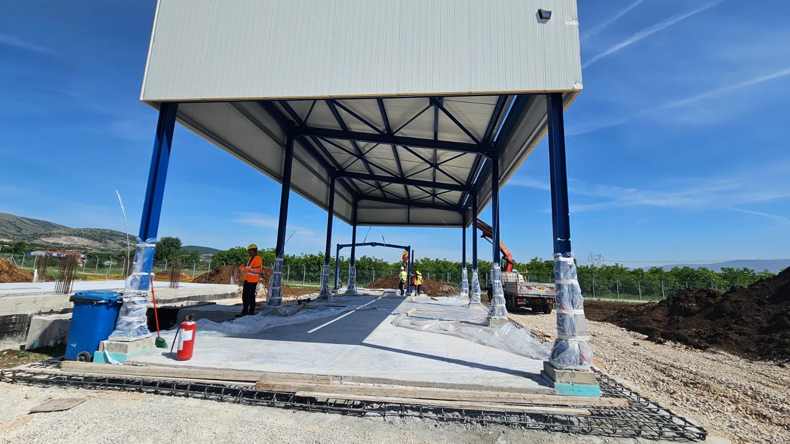
In practice: the Kardia metering station
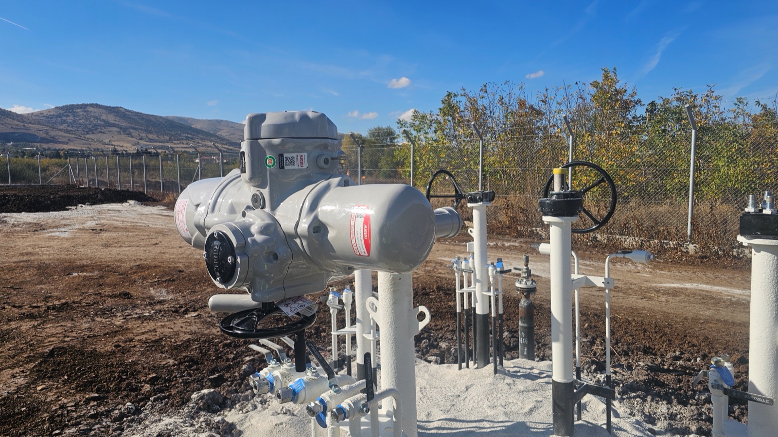
Meter types
These are the five technologies most often found in natural gas metering stations. The choice depends on the flow and its range, the pressure, the accuracy the contract requires and the maintenance. Each card leads to the detailed article by SEMAC Automation.
Ultrasonic meters (USM)
Transducers in the pipe wall send ultrasonic pulses diagonally, with and against the flow. The pulse travelling with the flow arrives slightly earlier; the time difference gives the gas velocity, and the velocity gives the volume.
Where it fits: Large flows and high pressure: transmission stations, interconnections, custody transfer with multipath meters. No moving parts, low pressure loss, and diagnostics on the health of the measurement.
Standards: ISO 17089-1 · AGA Report No. 9
Read more at SEMAC AutomationTurbine meters
The gas turns a rotor with angled blades. The rotor speed is proportional to the gas velocity; a sensor counts the passing blades, and each pulse stands for a known volume.
Where it fits: Medium and large flows of clean gas, in distribution stations and industry. Needs a flow conditioner and periodic checks of the bearings.
Standards: EN 12261 · AGA Report No. 7
Read more at SEMAC AutomationThe sketch shows an oval gear meter, the form used for liquids. For gas the same principle is applied with rotary impellers.
Positive displacement meters
The meter traps fixed volumes of gas one after another between rotating parts and the housing, and counts the revolutions. For natural gas the usual form is the rotary meter, with two figure-of-eight impellers (Roots).
Where it fits: Small and medium flows, with good accuracy at low flow rates too: industrial consumers and distribution stations.
Standards: EN 12480
Read more at SEMAC AutomationCoriolis meters
The gas flows through vibrating tubes. The mass flow slightly twists the vibration (the Coriolis force), and the phase difference between two sensors gives the mass directly, not the volume.
Where it fits: Smaller lines where mass is needed, such as compressed natural gas (CNG) stations; they also measure density. Also very widely used for liquids.
Standards: ISO 10790 · AGA Report No. 11
Read more at SEMAC AutomationDifferential pressure meters (orifice)
An orifice plate narrows the flow and creates a pressure drop. A transmitter measures the pressure difference upstream and downstream; the flow is proportional to its square root.
Where it fits: The classic, standardised solution: no moving parts, and an orifice plate sized by calculation to ISO 5167 and easily swapped for another flow range. Its range is narrower: because of the square root, a 1:100 range in differential pressure covers only 1:10 in flow.
Standards: ISO 5167-2 · AGA Report No. 3
Read more at SEMAC Automation
Station types
The same basic equipment is combined differently, depending on where the station sits and what else it does besides metering.
Metering station
Its purpose is metering: filters, meter runs, gas analysis and telemetry. It sits where large quantities change hands within the transmission system.
Our projects:
Metering and regulating station (M/R)
It meters and reduces the pressure, for example from the transmission network to the distribution network, or to the pressure a large consumer needs. It adds preheating, regulators and safety valves.
Our projects:
City gate station
A metering and regulating station where the transmission system feeds a city’s distribution network. It often also odorises the gas, so that a leak can be noticed.
Interconnection point
Where two transmission systems meet, for example at a border or where a new pipeline joins the national system. The measurement concerns two operators, so a second meter may be installed in series as a check.
Our projects:
On a skid or built on site
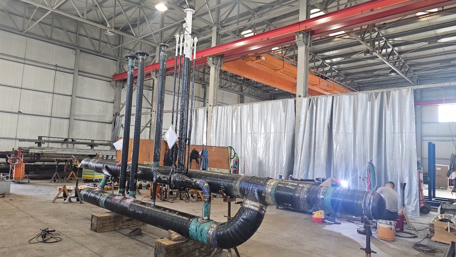
A station can be built and tested complete in a workshop, on a single frame (skid), and shipped ready; or it can be built on site, when its size or transport does not allow otherwise. A skid saves time on site and is tested before it leaves the workshop.
Our projects:
A skid in the workshop, a station on site
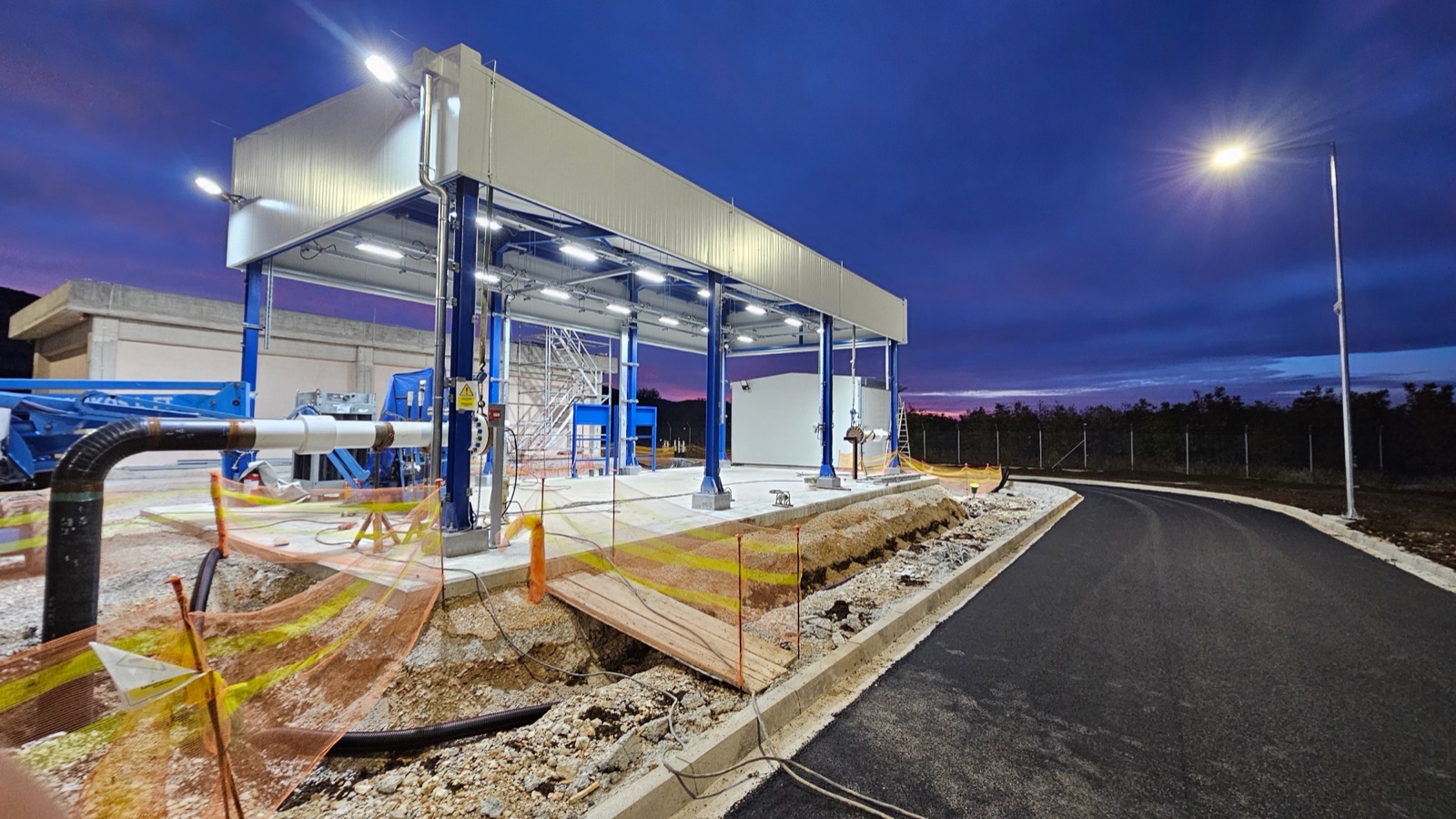
Liquids too
Liquid metering systems, for example at truck and ship loading or on product pipelines, follow the same logic, with three differences:
Meters: usually Coriolis, turbine, positive displacement or ultrasonic, chosen for the viscosity and temperature of the liquid. In-situ proving: the meter is often checked in place with a prover, a reference volume or master meter. The comparison gives the meter factor. Conversion: the volume is converted to a base temperature, usually 15 °C, with correction factors for temperature and pressure; the quality of the liquid, such as density and water content, is measured separately.
Standards and accuracy
Standards set how each part of the measurement is built, installed and checked. Which ones apply to a project is set by the contract and the network operator. The most common:
- EN 1776
Gas infrastructure — Gas measuring systems — Functional requirements
Design, construction and testing of the whole metering station.
- EN 12186
Gas infrastructure — Gas pressure regulating stations for transmission and distribution — Functional requirements
Stations that also regulate pressure.
- ISO 17089-1
Measurement of fluid flow in closed conduits — Ultrasonic meters for gas — Part 1: Meters for custody transfer and allocation measurement
Ultrasonic meters.
- AGA Report No. 9
Measurement of Gas by Multipath Ultrasonic Meters
Multipath ultrasonic meters.
- EN 12261
Gas meters — Turbine gas meters
Turbine meters.
- EN 12480
Gas meters — Rotary displacement gas meters
Rotary positive displacement meters.
- ISO 5167-2
Measurement of fluid flow by means of pressure differential devices inserted in circular cross-section conduits running full — Part 2: Orifice plates
Orifice meters.
- EN 12405-1
Gas meters — Conversion devices — Part 1: Volume conversion
Converting the volume to base conditions.
- ISO 6976
Natural gas — Calculation of calorific values, density, relative density and Wobbe indices from composition
Energy from the chromatograph analysis.
- OIML R 117
Dynamic measuring systems for liquids other than water
Liquid metering systems.
- API MPMS
Manual of Petroleum Measurement Standards
Metering of liquid hydrocarbons: provers, correction factors, sampling.
Calibration and verification
Calibration is the comparison of an instrument against a reference of known accuracy, traceable to national standards. It does not fix the instrument; it records how far off it is, so the deviation can be corrected or taken into account.
In a station, every part of the measurement is calibrated: the meter in a flow laboratory, before installation and at the intervals the operator sets; the pressure and temperature transmitters in place or in a laboratory; the chromatograph with a certified reference gas. The flow computer is verified with known input values.
Instrument calibration: services.semac.gr
For the laboratory calibration of instruments, the SEMAC Group offers its services at services.semac.gr.
Visit services.semac.grWhat we do
We take on metering systems from engineering to commissioning, complete (EPC) or in part.
Engineering
Detailed engineering and design of the station, technical studies, drawings and calculations, to the client’s specifications and international standards.
Procurement
Procurement of the equipment and materials: metering systems, piping, valves, instruments, electrical and control systems.
Workshop fabrication
Fit-up and welding of the piping, mounting of valves, actuators and instruments, factory inspection and testing, at our facilities in the Sindos Industrial Area.
Site construction
Foundations, buildings and control rooms, steel structures, process piping and valves, cabling, control panels and SCADA.
Instruments and calibration
Installation and calibration of the metering equipment and instruments by our team.
Testing and commissioning
Functional testing of all systems, performance verification and handover, with the mechanical completion book (MC book).
From our projects
Metering system projects
DESFA Kardia Metering Station (U-9430): Detailed Engineering, Procurement & Construction
EPC of the Kardia metering station (U-9430) for DESFA: accurate gas metering, system integration and reliable operation in the national transmission network.
View project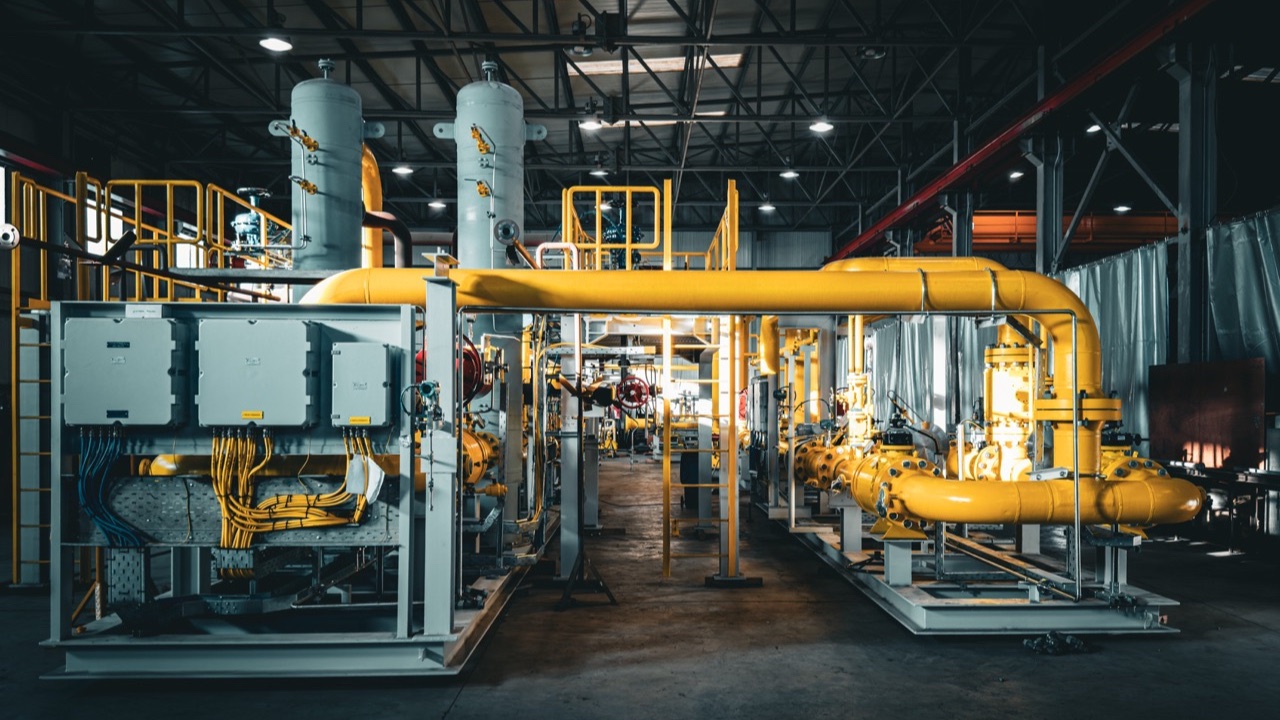
Gas Regulating & Metering Station for a Power Plant in Grudziądz, Poland
Complete design, manufacturing, shop testing and supervision of erection and commissioning of a skid-mounted gas regulating and metering station (GRMS).
View project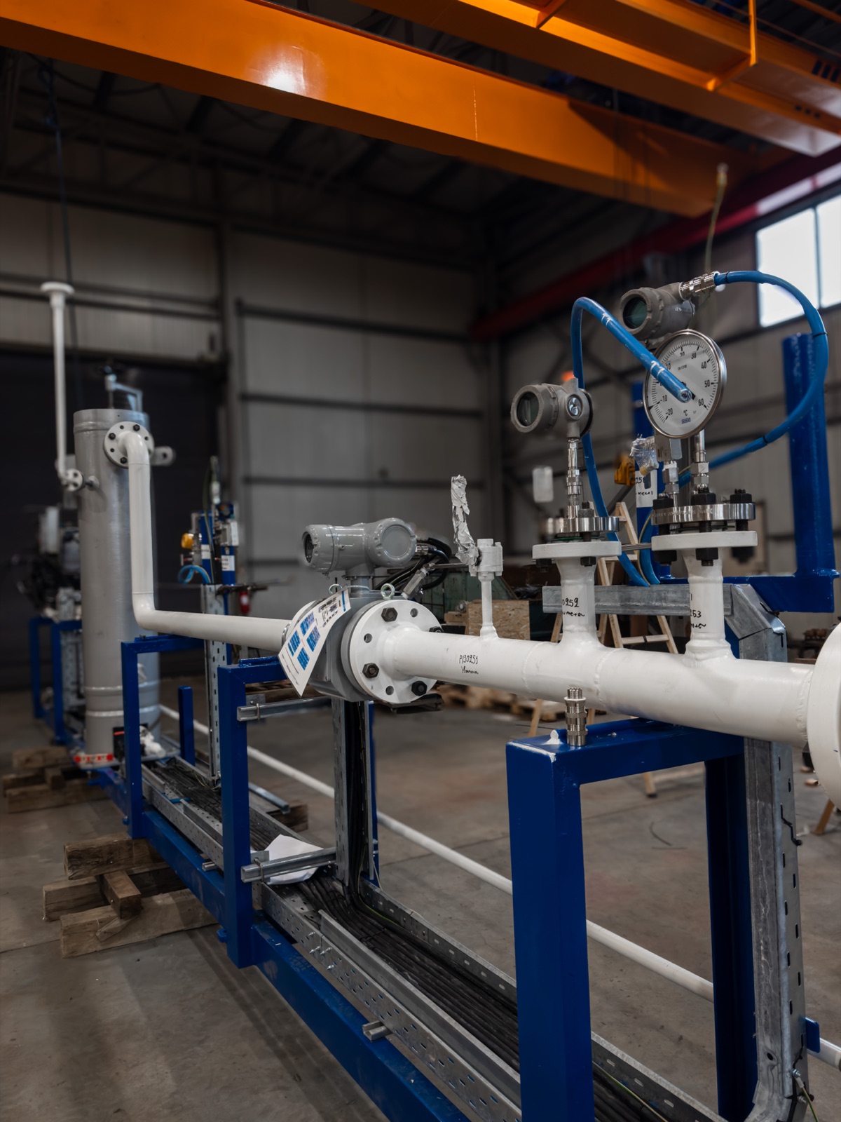
New Metering System for the 4th Metering Train at U-3020 Aghia Triada
A new metering system for the 4th metering train at the U-3020 Aghia Triada station, for accurate gas flow measurement across the full operating range.
View project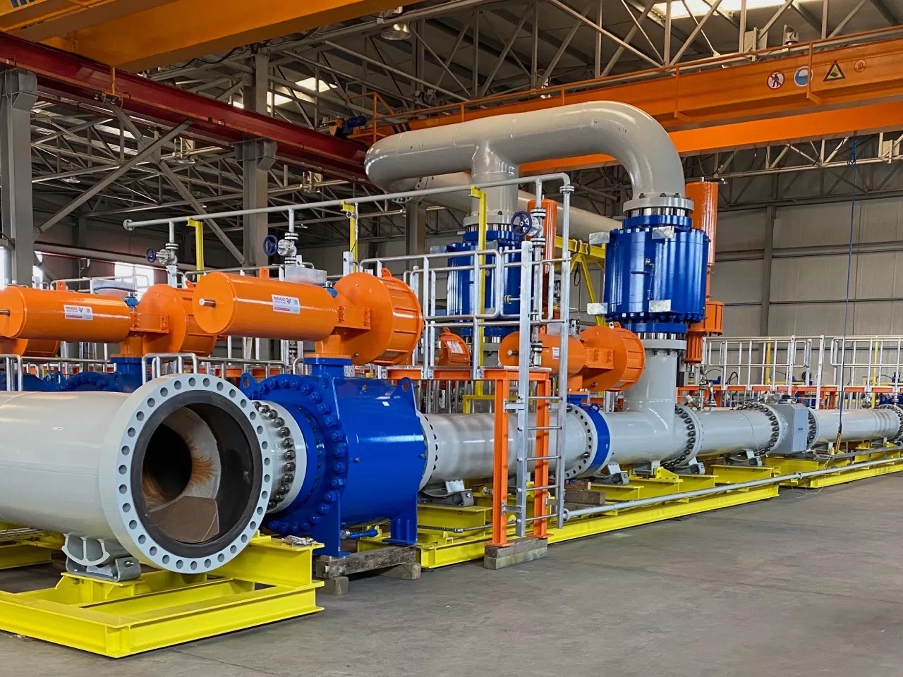
40-inch Natural Gas Metering System with Ultrasonic Flowmeters
A 40-inch natural gas metering system: two duty runs and one check/spare run with ultrasonic gas flowmeters, from engineering to shop tests.
View projectExpansion & Upgrade of the DESFA East (U-2220) and North (U-2240) M/R Stations in Thessaloniki
Detailed design, procurement, installation and commissioning of a third regulating/metering line at each station, with full equipment supply.
View projectFrequently asked questions
Short answers about natural gas metering systems.
Planning a metering station?
Tell us the flow, the pressure and what the station has to measure. Our team will get back to you.